Part 83: Assignment #AC8: Interface
InterfaceToday, I'm going to talk about weaknesses in organizational structures.
The fact that Avalon City expects you to self-organize is a great benefit, as it prevents a feeling of overwork and allows for a great deal of flexibility.
As a drawback, however, you can sometimes get almost (but not quite) press-ganged into helping with a project. It really depends on how the person asking makes the offer. (Asking politely can get you anywhere, but them being rude makes it feel... less fun.)
I guess what I'm really saying is that one of the drawbacks of the Avalon City organizational structure is one Mr. Kamran Farzan:

I said yes to the job, but yeah... I hope Mr. Farzan's not as brusque as that in person!
The NETHUNS project is one of Avalon's many, many research projects - its focus is on new ways of bridging the gap between human thought and computing. The only really notable thing about it is that this particular project is Sun-sponsored - it hews a little bit more multidisciplinary than some projects, though the team is arguably about as diverse (field-wise) as the Ocean's Bounty project was.
The actual project is part of a brain-computer interface - specifically, I think it's supposed to be part of a translation apparatus that converts nerve signals into data.
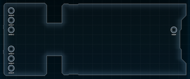
If I had to guess, once this component sends data to its output, the job of whatever-it's-attached-to will be to interpret the nerve pulses in some way.
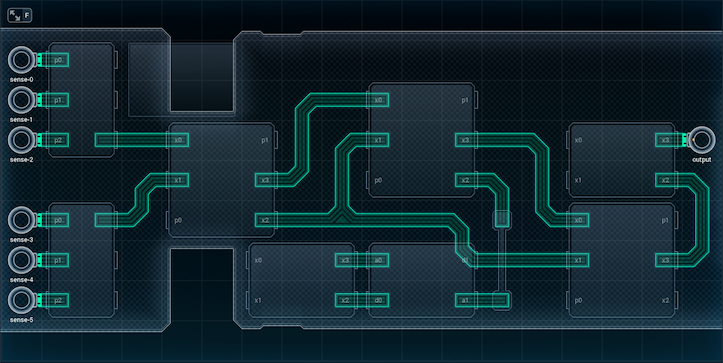
Design-wise, there's a few obvious places to start. Those six inputs just scream 'add input expanders'. Past that, there's three major design problems:
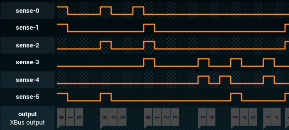
1. Counting how many pulses are active in a given time unit. From the test cases, it looks like a nerve pulse will never last two time units, so I don't have to worry about double-counting a pulse from the previous time unit.
2. Remembering how many pulses (and which pulses) were active in the previous time unit. If the device is reporting two time units' worth of pulses, the ones from the previous time unit will have to be saved so they can be reported.
3. Converting from three-digit (input expander) values to the 0-1-2-3-4-5 output values the interpreter (or whatever's on the other side of that output) expects.
Once I've figured out all those problems - well, that'll be the design!
[ ~ ]
Here's my first stab at it.

All three of the design problems are mentioned are solved.
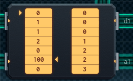
1. The device uses a RAM chip to turn the value from each input expander into a count of the number of '1's in the value. This works because each possible value from the input expander, when divided by 14, points to a separate location on the RAM chip:
'000' = address 0
'001' = address 1
'010' = address 10
'011' = address 11
'100' = address 2 (100 / 14 gives 2 left over)
'101' = address 3
'110' = address 12
'111' = address 13
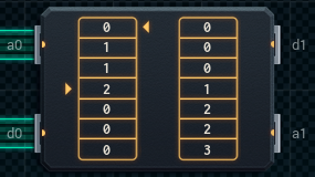
So, if you put [0,1,1,2] in the first four cells of a RAM chip, and [1,2,2,3] in the last four cells, feeding the input expander value to the RAM chip as an address will let you read the correct count as data.
The reason the device uses a RAM chip for this, as opposed to a non-writable memory chip, is that the RAM chip is also used for storing the last time unit's input values. More details when I discuss Design Problem No. 2, below.
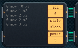
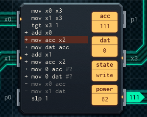
The fact that the design uses RAM means that I have to spend some chip space and instructions when the device is turned on to set up the eight values in memory. The far left MC6000 (the one connected to the input expanders) and the bottom left MC4000 are both responsible for this. The MC6000 on the left also passes on the input to be processed, and stores it in the RAM chip if need be - but the bottom left MC4000 is only used for setup.
2. The same RAM chip is used to store the values of the input expanders from the previous time unit.
In addition, the device keeps track of the count of 1's in the previous input - in the dat register of the MC6000 directly above the RAM chip. This counter MC6000 is responsible for getting the 1's count each time unit. It'll add the saved count back in the next time unit, using add dat.
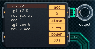
3. The two MCs on the far right are used to format the paired three-digit values into 0-1-2-3-4-5 output packets. The large formatter MC gets the data for the past two time units, amalgamates it by adding it together, and then sends each digit (one at a time) to the small MC. The small formatter MC checks if the digit it receives is a '1' or not, while keeping track of how many digits were sent previously in its acc. If a '1' is received, the small MC outputs its acc to the output pin. If it's a '0', it doesn't. Either way, it adds 1 to its acc, resetting it to 0 if it's over 5.
Effectively, the small MC goes through the numbers 0 through 5 in acc, sending those numbers to output if it received '1's, and not sending them if it received '0's. The pattern of 0s and 1s it receives determines what's output.
Here's how the device works from start to finish:
• At startup only, the input MC6000 and the bottom left MC4000 store the hardcoded values into the RAM chip.
• Each time unit, the input MC6000 on the left sends the input expanders' values to the counter MC6000 in the center. The counter MC counts how many 1's are in the input, adds the count from the previous time unit (which was stored in its dat), and sends that number back to the input MC.
The counter MC also resets the address pointer of the RAM chip so that other MCs can use it.
• If the input MC sees '2' or more, it will re-send the input to the counter MC so that the counter MC can pass it on to the formatter MCs. Otherwise, it will send the input to the RAM chip to store it for next time unit.
• The counter MC also checked whether the count was '2' or more - this is how it knows whether to expect more input or not. If the count is 2+, it sends this input on to the large formatter MC in the bottom right. Otherwise, the counter MC stores that in its dat to be added next time unit.
• When the large formatter MC gets input, it adds the previous time unit's input, which was stored in the RAM chip. Then, it sends each digit of the combined input to the small formatter MC, one at a time.
• The small formatter MC converts the digits to the output format the device expects, sends the output, and the cycle begins again with the input MC.
This design is ¥25, and uses 2112 average power per run, but... well, all the explaining I did when writing this up left me unsatisfied. Why do I need a RAM chip to store two values total, when I could use a ROM chip to store the translation table, put the last time unit's input in two registers, and save a MC?
I'm going to rebuild the design, aiming to make it a lot more efficient. Here goes.
[ ~ ~ ]

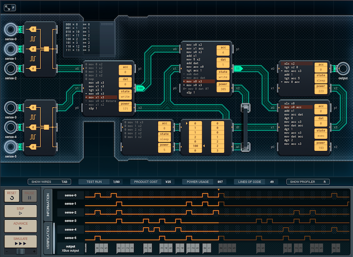
As promised, the updated design is a lot more streamlined.
The input MC6000 still sends the values from the input expanders to the counter MC (now a MC4000 in the top center), and receives a count of 1's in return. However, if the returned count is less than 2, the input MC will store the current time unit's values in its acc and dat, instead of in the RAM chip (which was removed; the 1's count table was moved to the ROM chip, attached to the counter MC.)
If the count is 2 or more, the input MC will add the previous time unit's values to the current input values before sending them to the large formatter MC (the bottom center MC6000) - previously, the formatter MC did this itself.
I realized that the counter MC doesn't need to keep track of how many 1s were counted in the previous time unit, because of the threshold of two 1's for sending data to the output. If no 1s were counted at all last time unit, or the device sent data to the output last time unit, then the counter doesn't have to add anything to the value. The only situation where the counter MC has to fiddle with the value is if there was exactly one '1' last time unit - and that data can be stored using conditional flags instead of dat. Because of this, I was able to cut the counter MC down to a MC4000.
Finally, the large formatter MC doesn't need to access the memory chip either, as the input MC does the addition of the previous time unit's input for it. Its script is slightly shorter for this reason, while the small formatter MC (the MC4000 in the bottom right corner) is exactly the same.
Here's the updated version of how the device works:
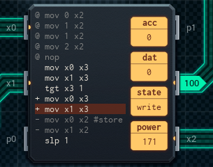
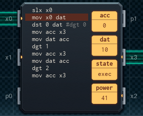
• Each time unit, the input MC6000 on the left sends the input expanders' values to the counter MC4000 in the center. The counter MC counts how many 1's are in the input; if it counted a single '1' last time unit, it'll add an extra one to the count now. It then sends the total count back to the input MC.
• If the input MC sees '2' or more, it will add the current input and the previous time unit's input (which was stored in its acc and dat) and pass the result on to the formatter MCs. Otherwise, it will store the input in its acc and dat for the next time unit.
If the input MC sent data to the formatter, it will clear its acc and dat so that values from before aren't double-counted.
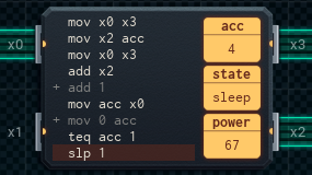
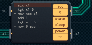
• The counter MC checks if it counted exactly one '1'. If so, its conditional flag sets up the add 1 next time unit.
If the conditional flag was already set going into this time unit, a line of code* will trigger, instead, that makes sure that the test fails. This clears the flag (because if we had only one 1 on the last time unit, the device will either send output this time unit, or it didn't receive any input this time unit - the flag needs to be reset either way).
*It's the + mov 0 acc.
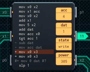
• When the large formatter MC gets input, it sends each digit of the combined input to the small formatter MC, one at a time. It uses the dst 0 dat trick to save a line of code - copying the three-digit input value to its acc and isolating the ones digit in the same line.
• The small formatter MC converts the digits to the output format the device expects, sends the output, and the cycle begins again with the input MC.
(This is unchanged from before.)
This version clocks in at ¥20, and power usage is also much improved - 1894 average per run! I'm happy with it, and I'll send it off. I wonder what Kamran and co. will think?
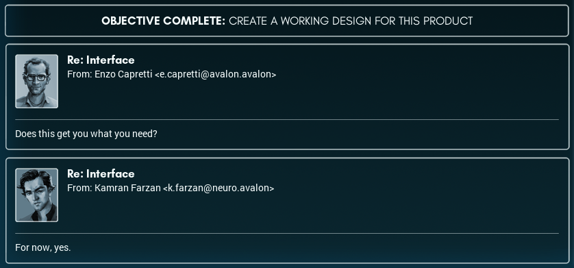
As terse as ever. Figures.
Interpersonal commentary aside, I'm sure I'll enjoy working on the NETHUNS project! It looks like it'll have intriguing challenges - and being back in research, on the forefront of something, feels good.
I'm looking forward to whatever they have for me next....